JCM2000 Stable Bias Mod
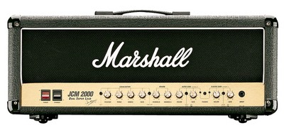
 The Marshall JCM2000 DSL50, DSL100, TSL100 and TSL122 amps are often troubled by an unstable bias (drifting bias). This can be difficult to diagnose correctly when the amp is on the repair bench as it can take half an hour or more of testing and/or playing before this bias drift manifests itself noticably. Due to this drift the bias current of the power tubes will gradually increase, and will keep increasing, until the power tubes will glow bright red/orange and the HT fuse will blow (sometimes). When this phase has been reached the power tubes are usually defective and will need replacing. Often this happens with two of the four (DSL100, TSL100 en TSL122) or one of the two (DSL50) power tubes, on the right hand side (as viewed from the rear of the amp).
All sorts of wild stories about this phenomenon circulate on numerous guitar amp forums but none of these stories address this issue completely and accurately. Dr.Tube has very thoroughly investigated this problem and has devised a simple and elegant but very reliable and affordable solution to this problem.
The Cause of the Bias Drift.
The primary cause is to be found in the main printed circuit board (PCB). That is the big PCB with all the tubes on it and we’ll call it the mainboard from now on. At first I thought the bias drift manifested itself only on the early mainboards (up to 2003 or so), but since then I’ve discovered that ALL the mainboards, including the “new” issue 20 mainboards, are troubled by the bias drift. It is very likely you allready have been, or soon will be, confronted with the bias drift problem.
Due to the heat produced by the tubes the mainboard PCB material becomes ever so slightly conducting. The root cause of this is called Conductive Anodic Filament failure (CAF). CAF is caused by heat, humidity and high voltages, exactly the conditions inside a guitar amp.
The specific layout of this PCB is such that some circuit tracks at the HT voltage (usually around 450V or so in these amps) run right next to the tracks for the negative grid (bias) voltage. At one location the distance between these two tracks is less than 1mm! When the mainboard becomes slighty conductive, due to CAF, the HT voltage will “pull up” the negative grid voltage, thus increasing the bias current. This is a runaway process and it wil only stop due to the power tube current saturating at some very high current (whilst going into meltdown mode) or the HT fuse blowing, but more often than not, the HT fuse blows too late (or not at all).
This problem has been ascertained on ALL issue mainboards! The early mainboards are also often fitted with the incorrect control grid resistors (issue 1: R55, R57, R62 & R70, all other issues: R7, R10, R66, R70). These are then 220kΩ instead of the desired 5.6kΩ. This will further aggravate the drifting bias problem.
Marshall used to offer a new mainboard (the so called issue 20 boards) as a “solution” for this problem. The supply of these boards has dried up. They are not available anymore. These issue 20 boards weren’t made to solve this bias drift problem, but to comply with the then new and strict RoHS legislation, which prohibits the use of lead and cadmium (and some other materials not relevant for this matter). The lead problem was solved with lead free solder. Cadmium is used in the LDRs of the NS32 optocoupler(s) used for the channel switching. The issue 20 boards now use a relay for this instead of the forbidden NS32 optocouplers. Unfortunatley, these issue 20 boards are also be troubled with the drifting bias problem as the problematic layout areas have not been changed or improved.
The Solution of the Problem.
 The solution for this problem is actually rather simple: remove all the bias components from the mainboard and place these on their own PCB isolated from the mainboard (and its high voltages). Pin 5 (the control grid) of the power tubes must then also be isolated from the mainboard. This is crucial!
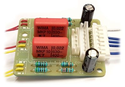
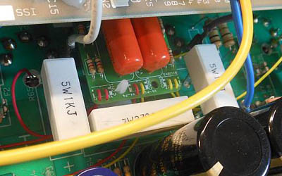
Dr.Tube has designed a small PCB (and a complete kit with all the necessary parts) which is easy to mount in these amps. This PCB is fitted with the new bias parts and is connected between the mainboard and the small bias pot PCB at the rear. The extra required cable is supplied with the kit. A couple of wires need to be connected between the mainboard and the new bias PCB. The mainboard needs to be slightly modified where all the pins 5 of the power tube sockets need to be freed from the mainboard. This can be done with a Dremel, but Dr.Tube can supply a very handy hollow drill making this part of the job a piece of cake!
 This Stable Biasmod Kit can be ordered as a kit in the Dr.Tube webshop. There is a version for the DSL50 en DSL100 amps and there is a version for the TSL100 en TSL122 amps.
Installing this kit requires more than average skills. You need to be able to correctly disassemble and reassemble a JCM2000 amp without losing any screws or having any screws left over when you’re done. The mainboard needs to be modified with a Dremel or a hollow drill and you need to be able to solder. All together this isn’t rocket science but if all this is new to you then it is probably wise to have this kit installed by an experienced tech. This kit can ofcourse also be installed by Dr.Tube. The installation costs are € 130,00.
For repair shops, amp techs, amp modders, etc. we also have a Full Kit of Parts available in the webshop. This Full Kit of Parts contains all the needed parts for both the DSL or TSL amps, so you only need to keep one style of kit in stock.


